
The Cairo SNARK CPU architecture in one example posted December 2021
I spent some days over Christmas to read the paper Cairo – a Turing-complete STARK-friendly CPU architecture. First, it's a work of art. I find a lot of the papers in the field of general-purpose zero-knowledge proofs (GP-ZKPs) quite hard to read, but this one has a lot of emphasis on the flow and on examples. More than that, the ideas contained in the paper are quite mind-blowing (although everything is mind-blowing in the land of GP-ZKPs).
What is this paper? It's the layout, in quite the detail, of a protocol that can be used to produce zero-knowledge proofs that a program executed correctly (what they call proof of computational integrity*). While most approaches "compile" each program into its fixed protocol (with a prover part and a verifier part), Cairo is a single protocol that works for any program (of some bounded size of course). They call this the CPU approach, as opposed to the ASIC approach. Effectively, the program you want to prove is encoded in some Cairo instruction set and passed as input to another program that will simply run it, like a VM. Translated in ZKP-lingo, a circuit will constrain the execution trace to match the execution of the program passed as public input. (This last sentence might be hard to understand if you are not familiar with at least one GP-ZKP system.)
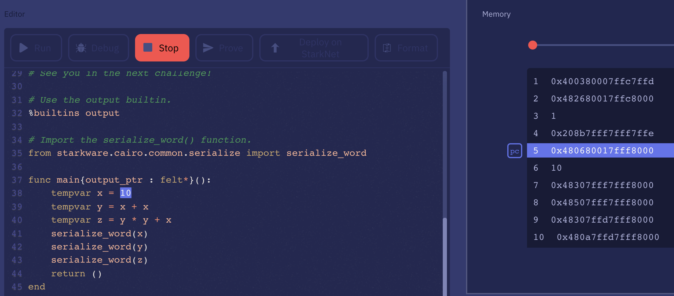
Cairo is also a higher-level language, that you can play with on the Cairo playground. If you click on "debug" you can see the program it compiles to. Essentially a series of instructions and data, which you can think of as code and data segments of a binary. The rest of the memory essentially acts as a "stack" that is used during the execution of the program.
The higher-level language is out of scope of the paper. Instead, the paper details the set of instructions and its encoding, which is then unpacked in the constraint of the circuit executing the program. In the paper, they go through a simple example, the Fibonacci sequence, to illustrate how a program works and how the state transition logic works. As I had to reverse engineer it I thought I would share this here.
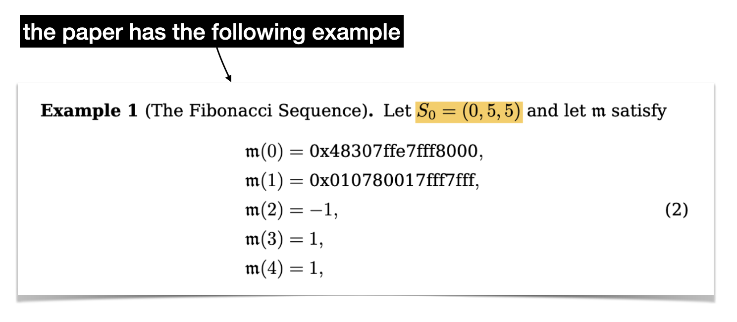
Here's our program, which is two instructions followed by three values.
Let's start simple and let's look at what the first instruction tells us.
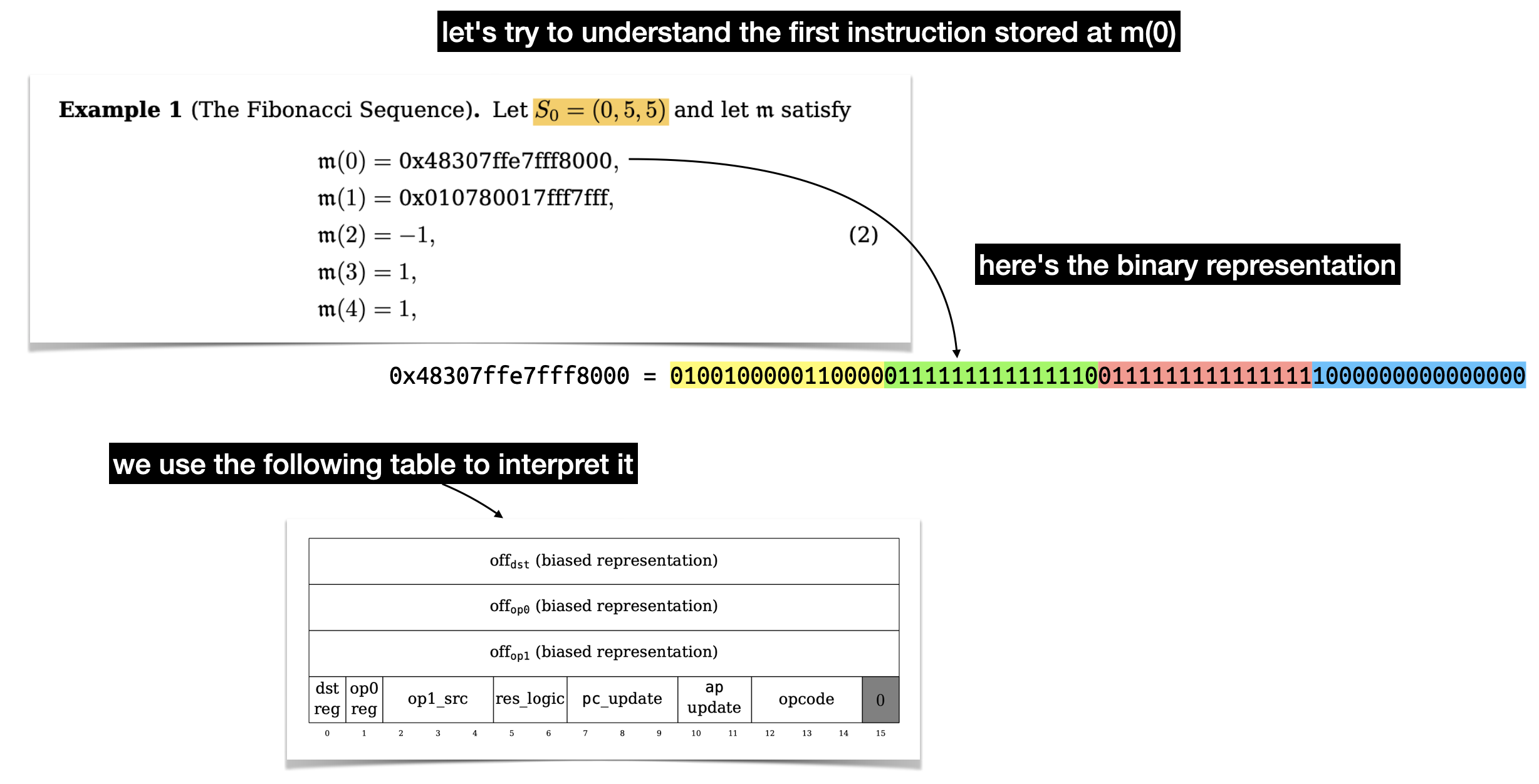
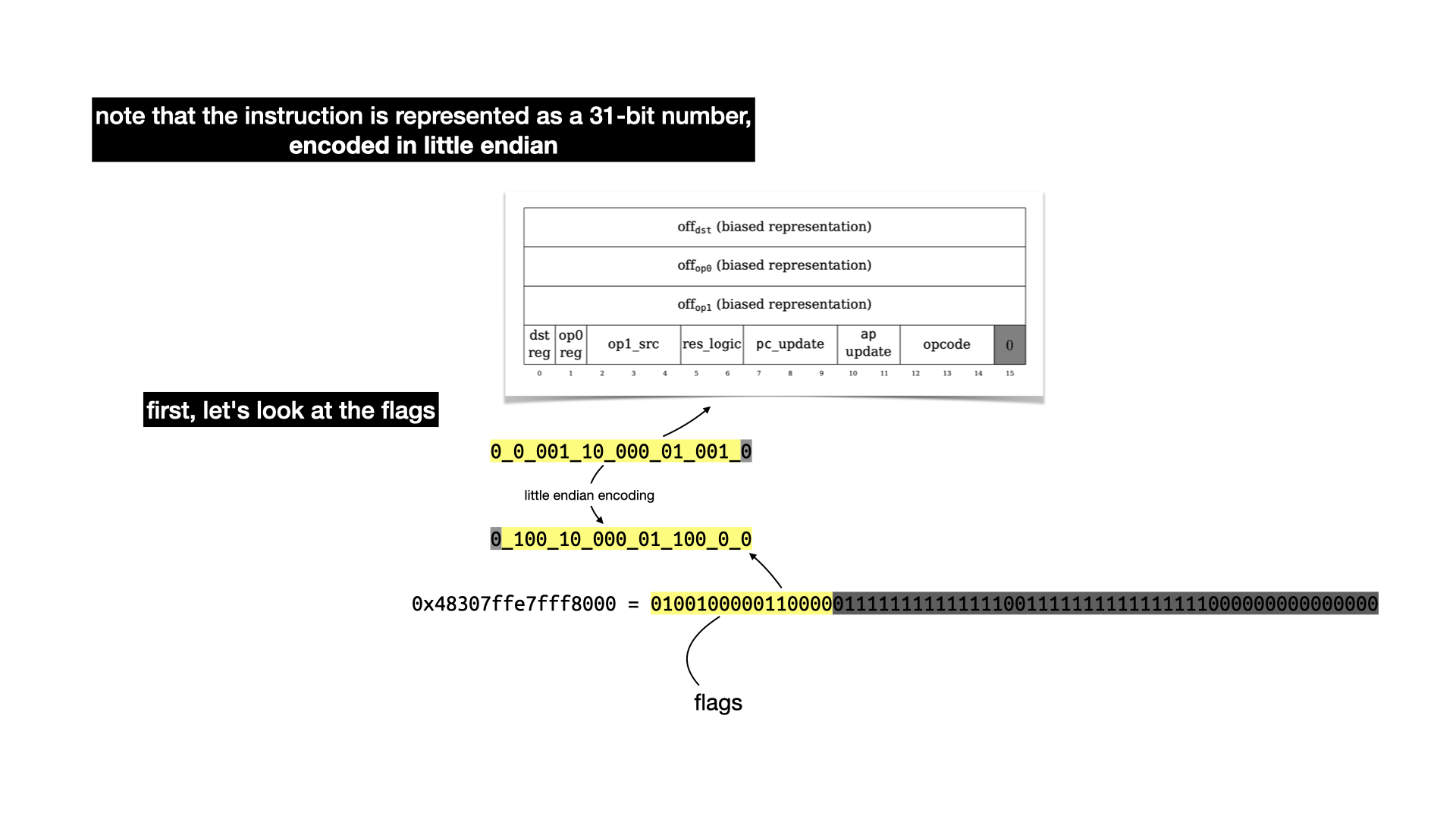
There's a lot to unpack here, there's three values of 16 bits that represent offsets in our memory. Two for the two operands (op0 and op1) of a binary operation, and one (dst) to indicate where to store the result of the operation. Let's ignore these for now and focus on the last part: the flags.
To understand what each flags do, you have to take a look at the state transition function. It's a bit confusing to follow, but there's apparently a Lean proof that it is correct (this field really keeps on giving).
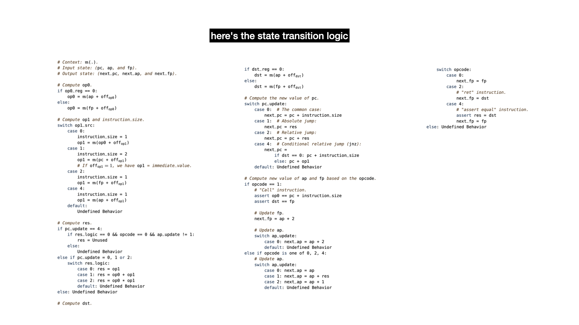
A lot of this is not going to make sense without reading the paper. But there's three registers:
pcis the program counter, it points to an address in memory from where to fetch the next instruction.apis the allocation pointer, it points to a free address in memory, useful to store data globally.fpis the frame pointer, used to store data as well when doing function calls.
The logic can be summarized as: fetch data from memory; operate on it (addition or multiplication); update the registers.
So what happens with our example's first instruction?
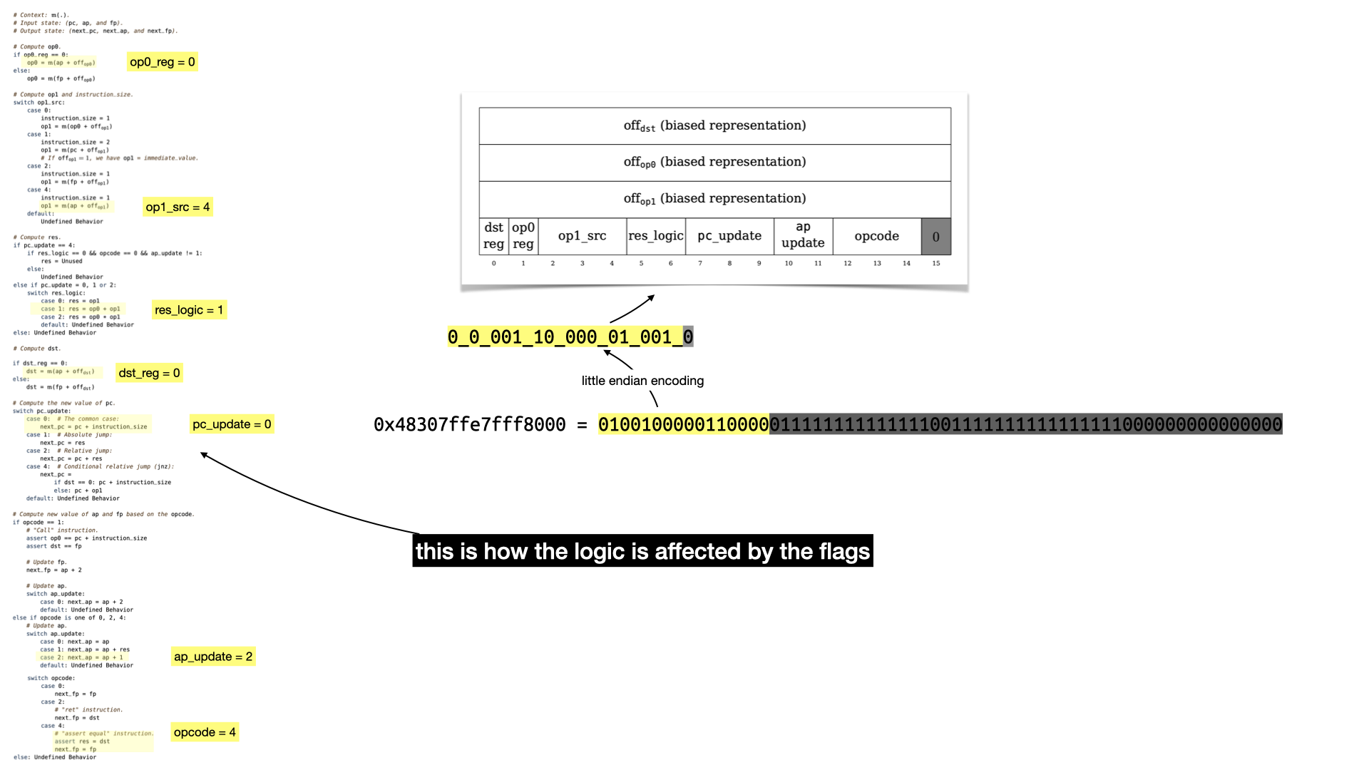
Still a bit abstract but that should give you an idea.
Before I reveal the result of the whole instruction let's look at the rest of the instruction: the offsets
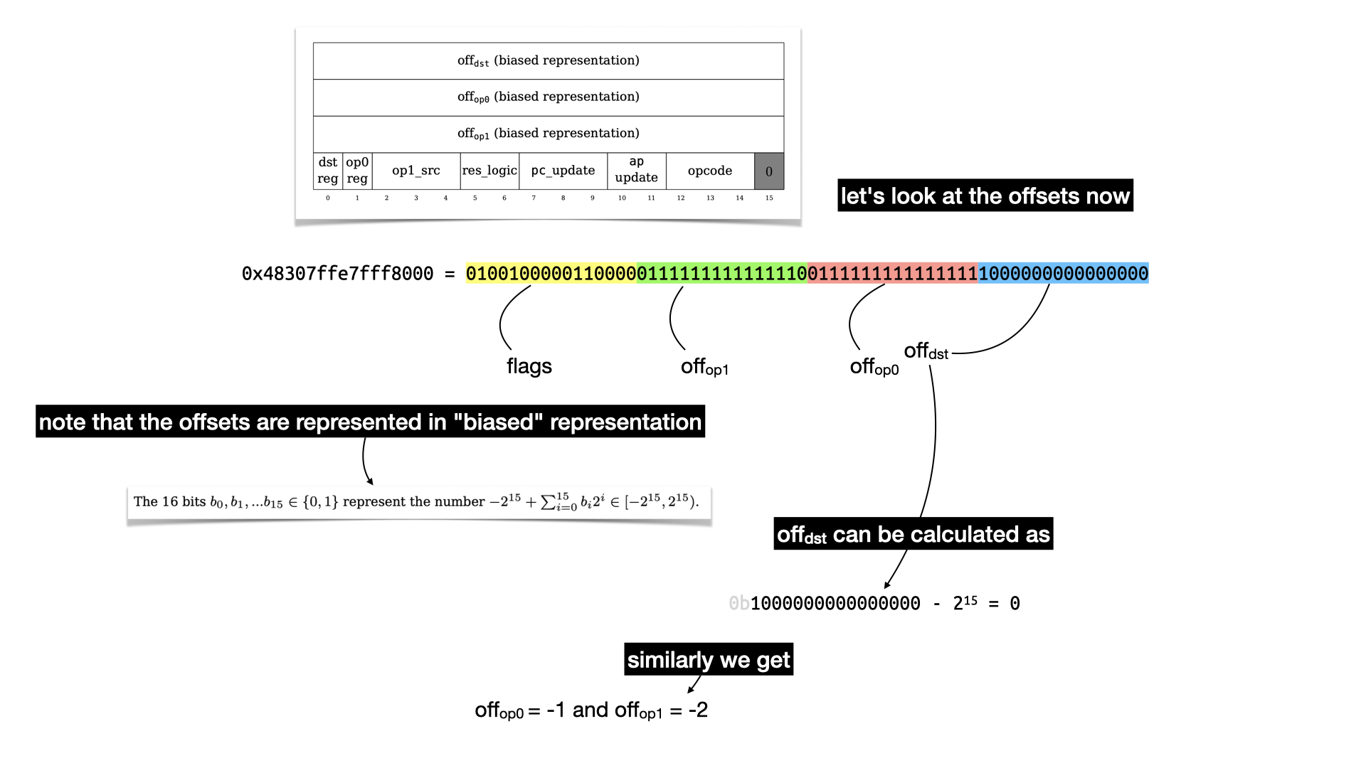
The offset leaks some of the logic: -1 and -2 are the indices in the Fibonacci formula
$u_i = u_{i-1} + u_{u-2}$
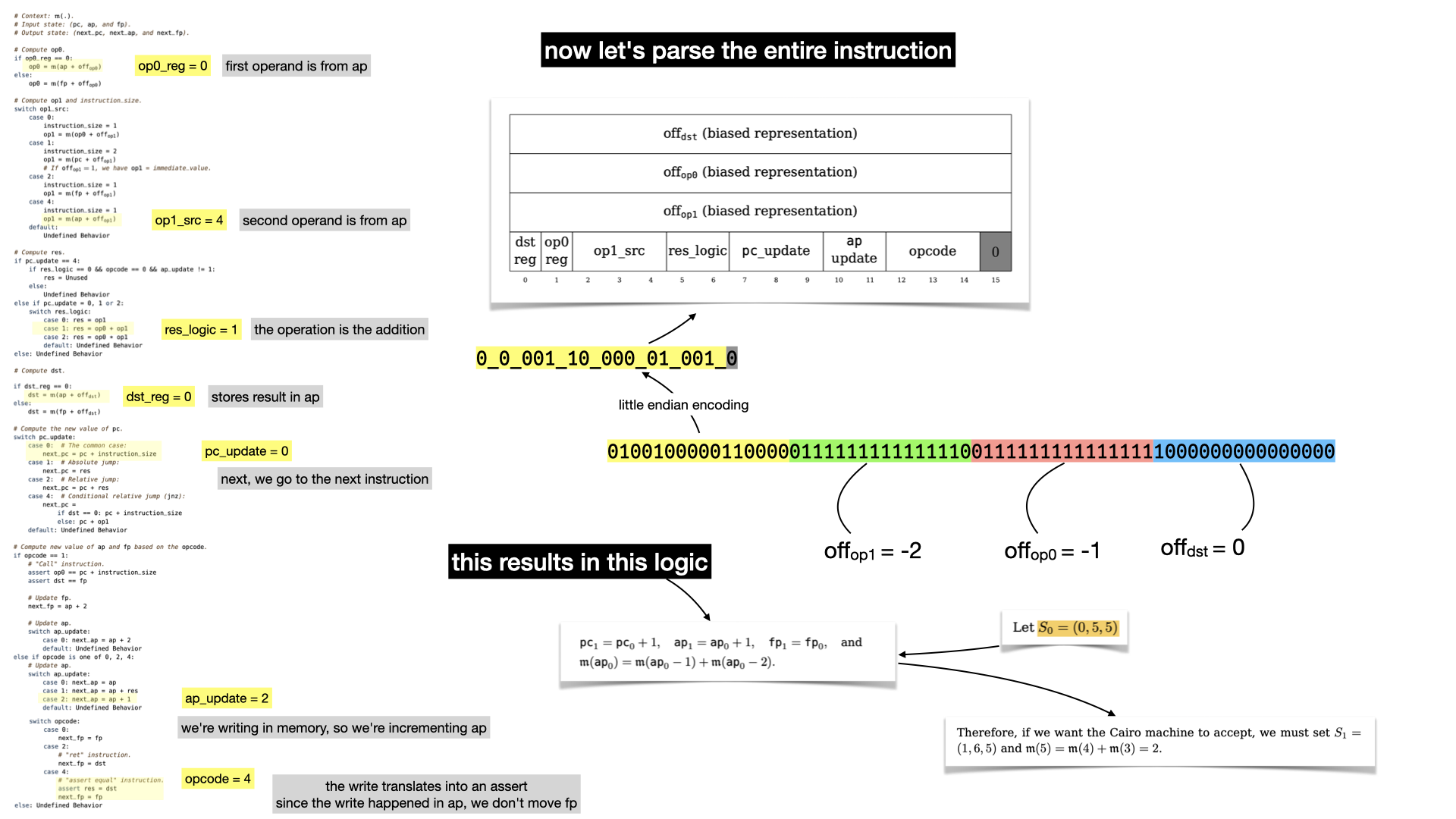
Let's now reveal what the first instruction is really doing.
There's no doubt that if you've followed that far you must have read the paper.
What happens can be summarized as:
- we increment the program counter
pc(to go to the next instruction) - we add the two values stored in the memory at offset
-1and-2, and store the result in memory. - we increment
ap, since we stored in memory. We don't touchfpsince we didn't do any function call.
Let's look at the second instruction.
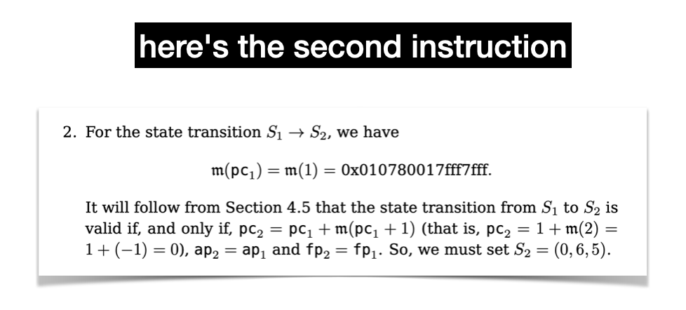
Let's reverse it using our table.
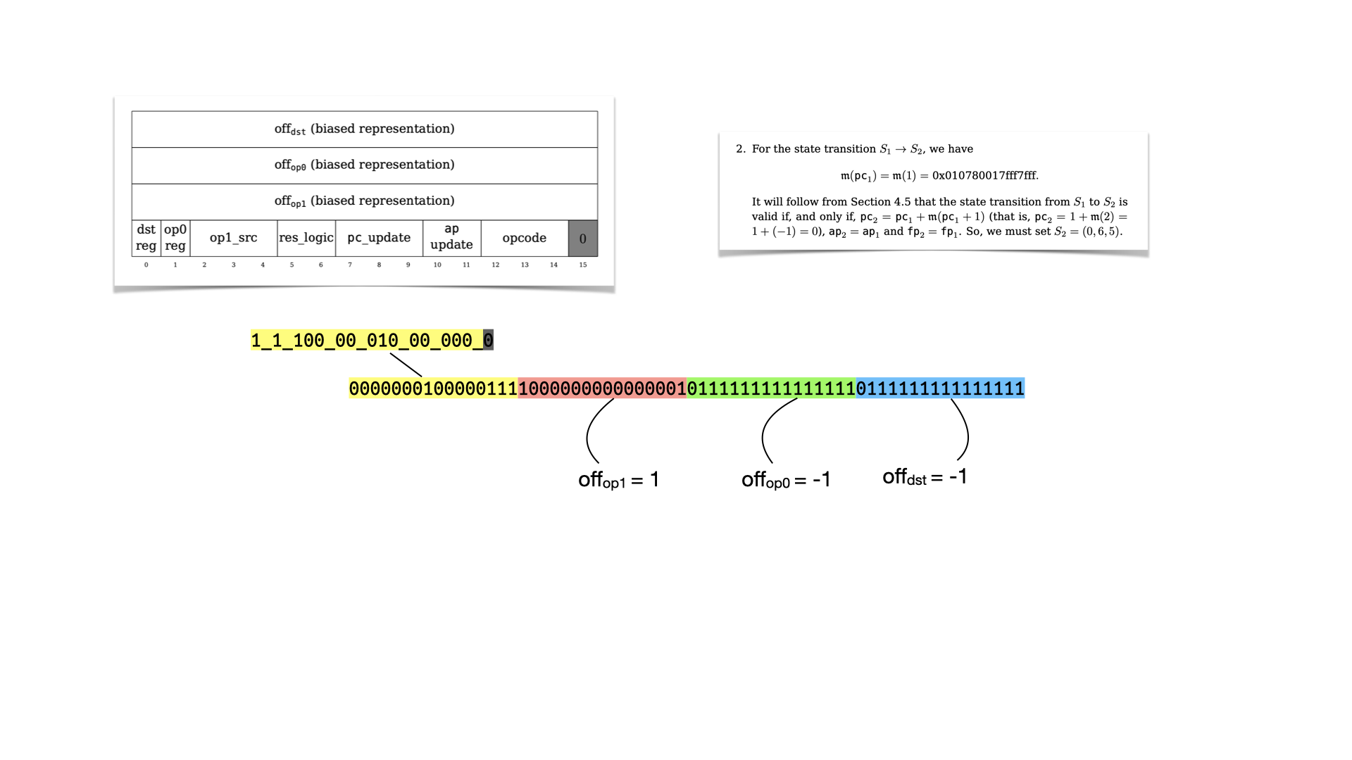
And let's look at the flags
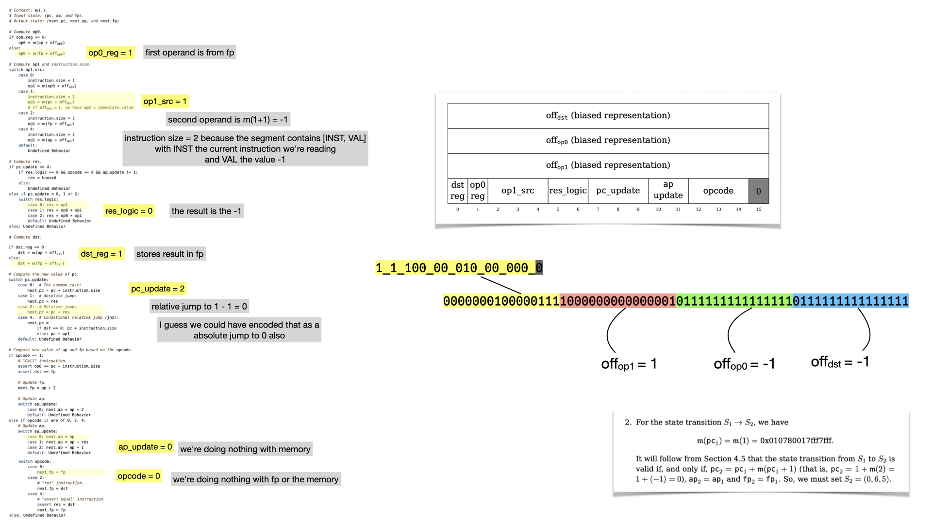
What's interesting here, is that the instruction leads to a jump! The next register values will lead to the circuit re-starting from instruction at memory address 0, because pc points to it. Thus, we're in an infinite loop, which is parameterized by the number of instructions that the prover wants to run.
Comments
sCrypt
SNARK -> STARK in title
leave a comment...